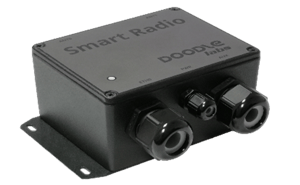
This Hardware Integration Guide provides information to facilitate smooth integration and use of the External Mesh Rider Radio.
The External Mesh Rider Radio is a small mesh radio, available in many frequency bands for deploying Private Wireless Networks.
Hardware Integration
The figure below shows how the Mesh Rider Radio can be integrated with a host system, along with some recommendations.

Fig. 2 External Mesh Rider Radio Hardware Integration
- Cable pairs should be twisted to reduce EMI. Note that USB cables should be twisted with GND.
- Power should be routed in a star topology; avoid unnecessary grounding loops.
- Adjust antennas (cross polarized or both vertical) to suit the application's needs. Please read the application note, Optimizing the RF Link for a discussion on long range optimization.
- The Mesh Rider Radio should be mounted on a suitable heat sink.
- Insert only a single jacketed wire harness through each cable gland
RFKill, UART, USB, GPIO
- The RFKill pin disabled in the latest revision of the Mesh Rider Radio
- The UART interface follows RS232 signaling levels.
- A single 5-V supply is provided which can provide up to 1 A of DC current (version 3 hardware only). It is recommended to twist the differential USB pair with GND and 5-V.
- GPIOs use 0 and 3.3-V logic and can source/sink. The maximum current source/sink capability of these pins is 25 mA.
Power Over Ethernet
Passive POE is available in the External version of the Mesh Rider Radio and in the Ethernet Test Kit. The diagram below indicates how Passive POE is implemented. The orange connectors represent the customer-facing connectors.

Additional Notes
The External Mesh Rider Radio does not include galvanic isolation.
Additional hardware Integration Guidelines can be be found on our Hardware Integration Guidelines page.
